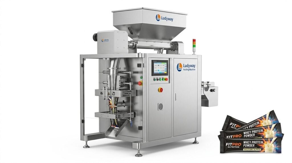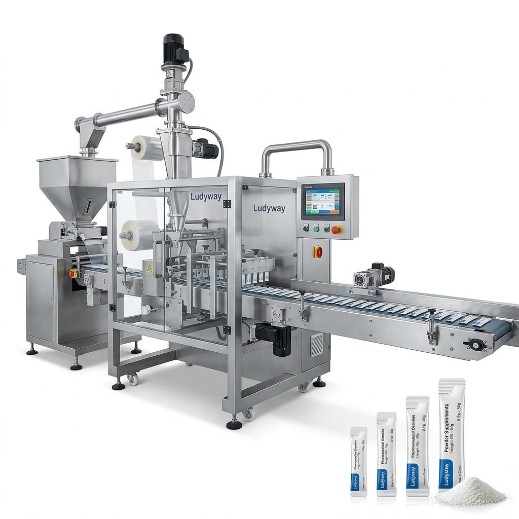
Packaging machines are the backbone of modern production lines, automating the process of enclosing products in protective materials for storage, distribution, and sale. Understanding their internal workings is crucial for operators, maintenance personnel, and business owners. This guide provides a detailed look at packaging machine diagrams, breaking down the different types, key components, and the fundamental principles that make them function efficiently and reliably.
Understanding Packaging Machine Diagrams
A packaging machine diagram is a schematic or technical drawing that visually represents the machine’s structure, workflow, and component layout. It serves as an essential blueprint for understanding how different parts interact to perform tasks like filling, sealing, and labeling. These diagrams are vital for troubleshooting, performing maintenance, and training new operators on the system’s operation.
Key Insight: Think of a machine diagram as a map. Just as a map shows roads and landmarks, a diagram shows the path of the product and the function of each mechanical and electrical station.
Primary Types of Packaging Machinery
Packaging machines are categorized based on their function, the form of packaging they create, and the type of product they handle. The main types include:
1. Filling Machines
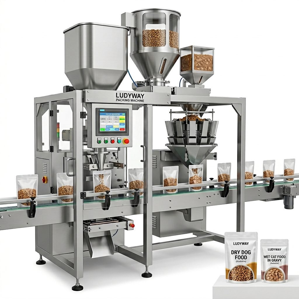
These machines measure and dispense a specific volume or weight of product into containers. They are critical for maintaining consistency and reducing waste.
- Auger Fillers: Ideal for powders and granules. An auger screw rotates to push product through a nozzle.
- Liquid Fillers: Use pumps, gravity, or pressure to fill bottles with liquids, from water to viscous sauces.
- Volumetric Cup Fillers: Utilize pre-measured cups for free-flowing products like seeds or snacks.
2. Sealing Machines
After filling, the package must be securely closed. Sealing machines apply heat, pressure, or adhesives to create a hermetic or tamper-evident seal.
- Heat Sealers: Common for plastic films. Heated jaws melt the film layers together.
- Induction Sealers: Create a tamper-evident foil seal under bottle caps using electromagnetic induction.
3. Form-Fill-Seal (FFS) Machines
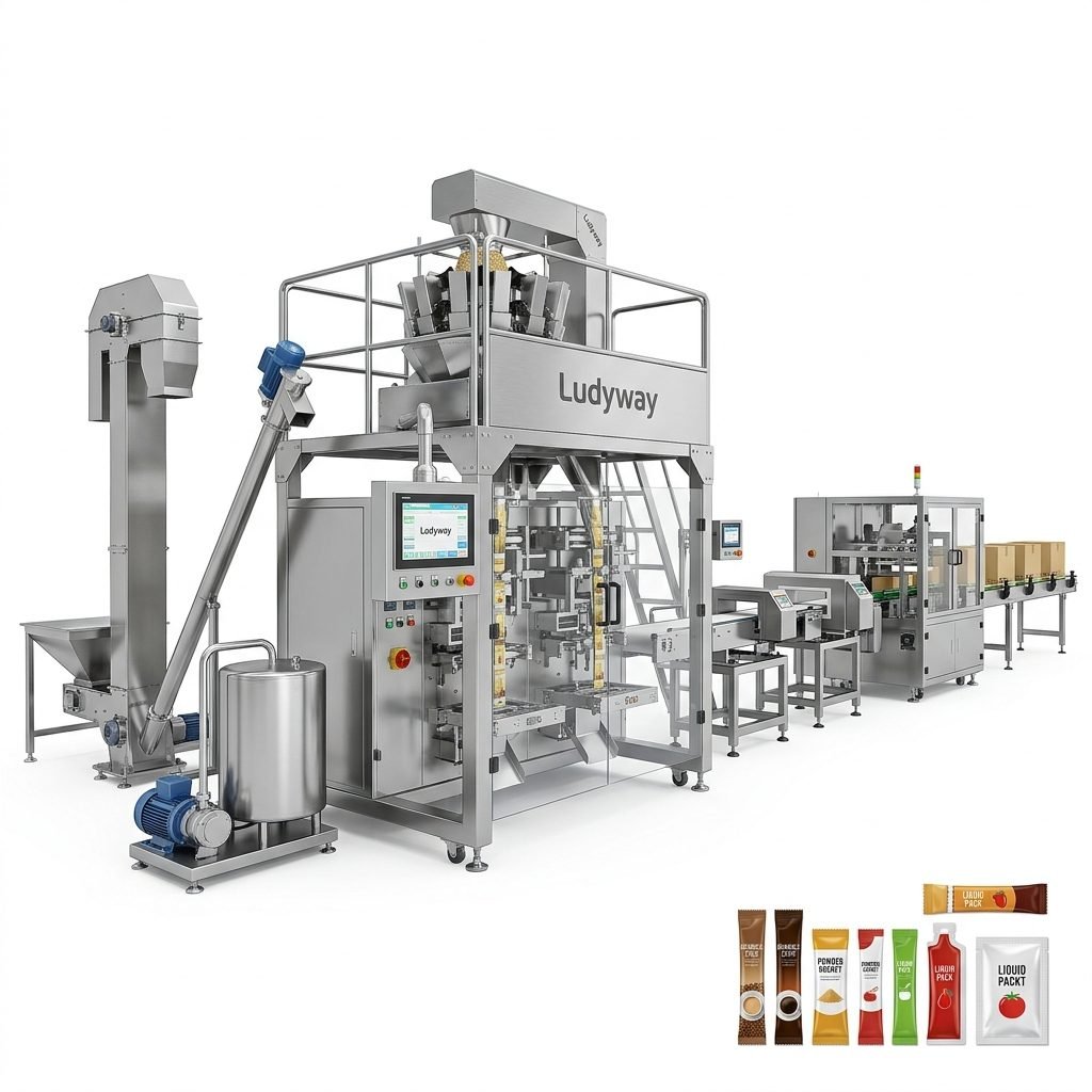
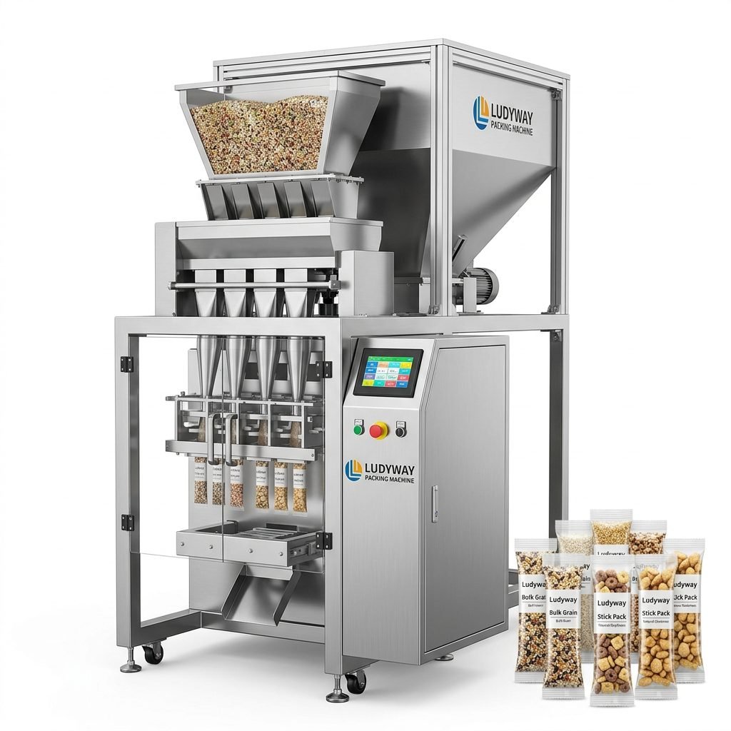
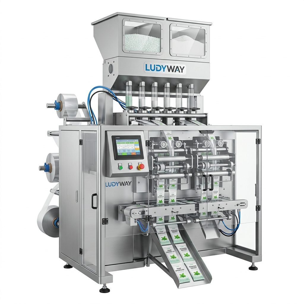
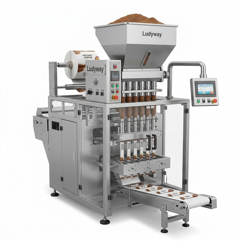
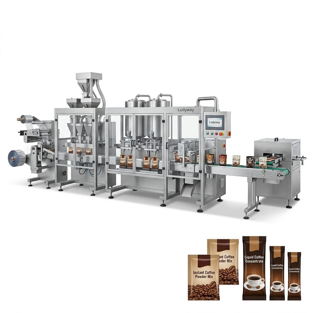
These are highly integrated systems that form the package from a roll of film, fill it with product, and seal it—all in one continuous operation. They are the workhorses for producing sachets and stick packs.
4. Capping and Labeling Machines
Cappers screw or press caps onto containers, while labelers apply product information, branding, and barcodes accurately and consistently.
Core Components in a Packaging Machine Diagram
While designs vary, most automated packaging machines share common core components that can be identified in any detailed diagram.
1. Frame and Structure
The rigid chassis that supports all other components. It is typically made of stainless steel or powder-coated carbon steel for durability and hygiene.
2. Product Feeding System
This subsystem handles the raw product. It may include hoppers, elevators, vibratory bowls, or conveyor belts that orient and deliver products to the filling point.
Component Spotlight: The Servo Motor
Modern machines extensively use servo motors for precise motion control. In a diagram, you’ll see them connected to drives and controllers. They allow for accurate positioning of film, precise filling stops, and high-speed synchronization, which is a hallmark of intelligent packaging machines.
3. Packaging Material Handling
This system manages the web of packaging film or the supply of pre-made containers. It includes unwinding rollers, tension control systems, and guide mechanisms to ensure material feeds smoothly and without wrinkles.
4. The Forming Section
In FFS machines, this is where the flat film is shaped into a package. A forming collar folds the film around a vertical or horizontal tube, creating the bag’s shape before sealing.
5. Filling Unit
The heart of the machine. Its design depends on the product:
➤ For Granules/Powders: An auger filler with a servo-driven screw.
➤ For Liquids: A piston or pump filler.
➤ For Solids: A pick-and-place or volumetric cup system.
6. Sealing and Cutting Mechanism
This station creates the final package. Heated sealing jaws (often with Teflon coating) press together to melt and seal the film. Immediately after, a cutting blade or hot knife separates the individual package from the web.
7. Control System
The machine’s brain. Represented in diagrams by a PLC (Programmable Logic Controller) symbol, touchscreen HMI (Human-Machine Interface), and various sensors (photoelectric, proximity). This system coordinates all movements and processes.
8. Drive and Transmission
This includes motors (servo, stepper, AC), gearboxes, belts, chains, and cam mechanisms that convert rotary motion into the specific linear or intermittent motions required for packaging.
Working Principles: How the Components Work Together
The operation follows a precise, cyclical sequence. Let’s trace the journey of a product through a vertical form-fill-seal (VFFS) machine, a common type for packaging snacks or powders.
Step 1: Film Feeding and Forming
A roll of packaging film is mounted on an unwind shaft. The film is pulled over tensioners and guides, ensuring it runs straight. It then passes over a forming collar, which shapes it into a vertical tube around the filling cylinder.
Step 2: Longitudinal Sealing
As the film edges overlap around the tube, a vertical sealing bar applies heat and pressure, creating a continuous back seam. This seals the film into a tube.
Step 3: Cross Sealing and Package Separation
Two sets of horizontal sealing jaws perform a dual function. The upper jaws close to seal the top of the finished bag below. Simultaneously, the lower jaws close to seal the bottom of the new bag being formed above. Between them, a cutting mechanism separates the finished package, which then drops onto a conveyor.
Step 4: Product Filling
This happens concurrently with Step 3. The product is dispensed from a hopper through the filling cylinder into the center of the film tube. The filling cycle is timed so that the product is in the tube before the lower cross-seal closes, trapping it inside the newly formed bag.
Principle in Action: Synchronization
The entire process is a ballet of perfectly timed movements. The PLC receives signals from encoders on the main drive and various sensors. It uses this data to command the servo motors controlling the film pull, jaw movement, and auger rotation. If any component is out of sync, it can lead to film jams, incomplete seals, or inaccurate fills.
The Importance of Reading Diagrams for Efficiency
For operational staff, the ability to read a machine diagram translates directly to higher productivity and lower downtime. It enables faster diagnosis of issues—for example, identifying a faulty sensor symbol on the electrical schematic or understanding how to adjust the timing of a cam from the mechanical layout. For businesses investing in turnkey production solutions, these diagrams are part of the crucial documentation that ensures long-term, reliable operation.
Frequently Asked Questions (FAQs)
1. What is the most critical component in a packaging machine diagram?
While all components are important, the control system (PLC) and servo drives are often considered the most critical for modern machines. They are the intelligence and precision behind the high-speed, synchronized operation. A failure here typically stops the entire line.
2. How can I use a machine diagram to reduce maintenance time?
Diagrams provide a roadmap. By studying the pneumatic diagram, you can quickly locate and isolate a faulty valve. The lubrication chart shows all grease points. Having these diagrams accessible allows maintenance teams to plan interventions and source correct spare parts before a breakdown occurs, significantly reducing repair time.
3. What’s the difference between a mechanical diagram and an electrical schematic?
A mechanical diagram shows the physical parts, their arrangement, and how they move (gears, cams, linkages). An electrical schematic uses symbols to represent the wiring, sensors, motors, and controllers, detailing how the machine is powered and controlled. Both are needed for a complete understanding.
4. Are diagrams standardized across different machine brands?
Basic symbols for common components (motors, sensors, valves) are somewhat standardized (following ISO or IEC norms), especially in electrical schematics. However, the overall layout and detail level can vary significantly between manufacturers. Always refer to the specific manual provided with your equipment.
5. How do diagrams help with training new operators?
Diagrams transform abstract machine functions into a visual story. Trainers can use them to explain the product flow, point out safety-critical components, and help operators understand the cause-and-effect relationship between controls on the HMI and physical actions in the machine, leading to safer and more competent operation.